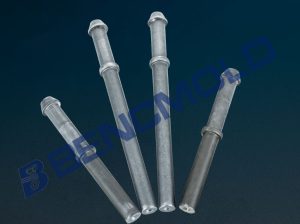
Most cold heading tooling lives inside a solid die, and for most fasteners that is exactly right. Then a part comes along with a shape that has no way out. A collar wider than the shank behind it. An undercut groove cut back into the profile. A head that overhangs a body the die would have to drag across. In each case the die has formed the part correctly and then cannot release it.
That is the case split die cold forming exists to solve. BENC MOULD has been building this tooling since 2008 and holds the patent on the multi-petal variant, applied for in 2013. This page covers how the technology works, where it earns its cost, and what it takes to develop a split die for a new part.
Why a solid die cannot release the part
Cold forming works because the die constrains the material radially while the punch drives it axially. The die is, by design, a closed ring. That is a strength until the finished part is wider somewhere in the middle than it is at either end.
Take a long pin with three collars along its length, or an anchor with an expansion cone that opens out below the shank. The die has to contain the widest diameter during the forming stroke, which means at ejection it also has to pass that widest diameter back out through the same bore. It cannot. The part is trapped by its own geometry.
Conventional practice is to accept the trap and machine the problem away: form the body, then turn the collars or the taper as a second operation. That works, and it costs you a second machine, a second setup, the scrap from the cut, and a grain flow that stops at every machined surface.
How the split die opens
A split die is not one ring. It is two, three or four segments that together form the die cavity during the stroke, then separate radially once the punch withdraws.
While the punch is travelling, a compressive stress ring holds the segments closed against the forming load. The segments carry the full radial pressure of the material flow, which is why the fit between them has to be exact and why the closing ring has to be stiff. On the return stroke the constraint releases, the segments move outward, and the finished part lifts clear with every undercut and collar intact.
The practical difference from a solid die is that the cavity is now an assembly rather than a bore. The parting lines have to close with no step. Any mismatch shows up twice: as a seam mark on the part, and as a stress riser in service. This is the part of split die work that is genuinely difficult, and it is where most of our development time goes.
What we changed to make it production-worthy
A split die that works once in a trial is not a split die that runs. The failure modes are specific, and they are the ones we designed against.
Petal clearance, optimised for speed
Our multi-petal split dies run with a tuned clearance between segments. Too tight and the segments bind and wear at the parting line as the die heats. Too loose and material flashes into the gap, which then has to be trimmed and leaves a mark. After years of iteration on this clearance, the dies run stable and smooth under high-speed continuous production rather than only at hand-feed rates.
Impact resistance at the parting edge
The parting edge on a die segment is a thin, highly loaded lip. Under repeated impact it is the first thing to collapse, and a collapsed edge means a seam on every part afterwards. Our segment geometry and heat treatment are set so the edge resists chipping and does not collapse under sustained production impact.
Configurations built to the part
We customise two-piece, three-piece and four-piece opening and closing dies to drawing or sample. The number of segments is not a catalogue choice — it follows the geometry. A part with two opposed undercuts wants two segments; a part with undercuts in several directions needs the cavity divided further so each segment can withdraw along its own path.
The dies are built to suit multi-station cold heading machines of any brand, so the tooling is not tied to one press make.
Where split die cold forming pays for itself
The economics are simple: a split die costs more to build than a solid die, and it removes one or more secondary operations for the life of the tool. It pays back on volume, and it pays back fastest where the operation it replaces is slow or the material is expensive.
- Hollow rivets and sleeves — formed and released without a separate punching or machining step
- Flange screws and collared fasteners — the flange or collar no longer blocks ejection
- Long-length parts with multiple collars — hinge pins, clevis pins and special studs where several collars sit along a slender shank
- Wedge anchors and expansion anchors — the expansion cone is formed rather than turned, keeping grain flow through the highest-load section
- Special-shaped and non-standard components — spring clips, clamps and retaining parts with profiles a round die cannot produce
Two working examples
Automobile hook drop screw on a 134LL cold former
This part is formed on a 134LL long-stroke multi-station cold former with custom split die tooling. The head, the long shank and the multiple intermediate collars are all formed in a single cold forming run, with no secondary turning.
The difficulty on a part this long and this slender is not the collars themselves — it is keeping the shank straight. The material has the least radial support at mid-length, so that is where bending and eccentricity appear. We run forming simulation on the reduction sequence before cutting the die, and place the guide lengths so the shank stays true through the stroke. Finished parts keep continuous grain flow, which is what gives them their fatigue performance in construction machinery, automotive and hydraulic service.
Wedge anchors, one shot, no taper turning
An anchor has the most extreme release problem in this family: an expansion cone that opens out below the shank and a retaining groove that cuts back behind it. Formed in one pass on a multi-station cold former with split die tooling, the cone, shank and retaining structure all come out of the die complete. The tapered end is never touched by a lathe.
The result is a part whose grain flows continuously from shank into cone, with the cone, shank and groove held concentric from a single clamping. Full detail on that process is in our wedge anchor split die case.
How we develop a split die
Split die development is process work before it is machining work. A die that is cut before the process is settled will need to be cut again.
First, the release question. We look at the drawing and ask whether the part can be ejected from a one-piece die at all. If it can, a solid die is cheaper and we will say so. Split tooling is only worth its cost when the geometry genuinely demands it.
Second, the segment split. Where the cavity divides decides whether each segment can withdraw without dragging across a formed surface. This is where the part geometry and the die design negotiate, and it usually has more than one workable answer.
Third, the forming sequence. The number of stations, the reduction at each, and the guide lengths. On long parts we verify this with simulation before committing to steel.
Fourth, the build. Segments are wire-cut, then fitted and marked as a matched set. They are not interchangeable between dies, and they are supplied together with their closing ring, because a new segment in a worn ring will not close correctly.
What we hold, and on what machine
Two factories under one roof: one dedicated to cold heading dies and fastener forming tooling, the other to punches and punch heads. A complete split die set — cavity segments, closing ring, punch, sleeve and knock-out — is finished and shipped together, so the tolerances are married before the customer sees them rather than after.
More than 30 sets of precision processing equipment across the two plants: CNC lathes holding 0.002 mm, cylindrical grinders holding 0.005 mm on the outer diameter, internal grinders for bore and bore taper, wire-cut and die-sinking EDM for the segment geometry and undercuts. Inner diameter precision is held within 0.01 mm with high concentricity, verified on profile projectors, vision measuring machines and concentricity gauges before shipment.
The patent, and why it matters to a buyer
We developed the multi-station split die in 2008. In 2013 we applied for patent protection on the technology, which is specifically aimed at the problem of automatic opening and stripping after a conventional integral master die has formed a part it cannot release. The patented claim sits on the opening and stripping mechanism itself, not on the idea of a segmented die.
For a buyer, the relevance is not the certificate. It is that this tooling has been in continuous production since 2008 and the current design is the result of iterations on clearance, edge geometry and segment count that a first-time builder would have to discover the hard way. We have also seen the process imitated; what is harder to copy is a decade and a half of knowing which failures to design out.
What to send us
Split die tooling across the cold forming families
Split dies are one capability inside a wider tooling range. The same plant builds solid cold heading dies for the standard case, cold forging dies where the part needs forward or backward extrusion rather than simple upsetting, and split tooling where the release geometry demands it. Which family a part belongs to is decided by its shape, not by customer preference, and we will tell you when a cheaper solid die will do the job.
The distinction that matters in practice: a cold heading die upsets a billet into a head and shank within a closed cavity, while a cold forging die has to move material axially — extruding a shank down, or back-extruding a bore into the head. Those two needs put different demands on the die: the heading die is loaded in radial compression, the forging die in axial material flow against the bore wall. A split die can serve either, but the segment design changes with it.
A great many cold heading moulds (冷镦模具) in service today are solid cavity dies, and for a standard screw or rivet that remains the right and cheapest answer. Split tooling enters the picture only when the part has geometry that traps it, which is the whole subject of this page.
To evaluate a split die project we need the part drawing, the machine model and station layout you intend to run it on, the material specification, and the tolerance that actually matters to the application rather than the one on the title block.
If the part currently needs a turning, milling or punching operation to be released or finished, send that process sheet as well. Comparing the existing route against a one-shot split die route is how we establish whether the change pays back, and at what annual volume.
We will come back with the segment configuration, the die material, the station sequence, the tolerance we can hold and the tool life you should expect. From drawing to running die, development stays in our hands — request a quotation, or see our split die product range, cold heading die capability and full tooling range.
How those segments are made, and what the rest of the station set has to do to support them, is covered in our guide to cold heading dies for screws and bolts.